


 |
Membrane BioReactors Primer Need to know more? Send us an email or feel free to search our online series with our give away search engine: |
 |
The inexorable increase in sanitary requirements in effluent treatment systems, as well as the progressive availability and competitiveness of different types of materials, has led to an increasing application of membrane-type filtration systems in effluent treatment plant environments.
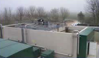 In reality, rather than developing entirely new technologies, conceptually it's "simply" an extension of classic water conditioning systems—long used for process water, drinking water treatment, and other applications—into new areas. Naturally, and quite selectively, especially in small installations, we see successful examples of microfiltration and ultrafiltration implementing unit processes historically achieved using sand filters, mixed granule filters, and even secondary clarification.
As with any new field of application, concrete results don't always align with expectations, especially when those expectations are based on commercial literature. It's clear that both the industrial and municipal sectors are eager for better methods and alternatives, but as with the disappointment surrounding diffuse aeration technologies (re: Musterman; ASCE curves), evaluation in the field of "new ideas" takes time.
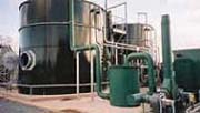
Nowadays there is much greater knowledge and experience in the assembly and operation of membrane systems, particularly in process water and drinking water treatment. It is with this caution that we incorporate "old technologies" such as micro- and ultrafiltration into the arsenal of unit processes in new contexts, i.e., biological wastewater treatment plants.
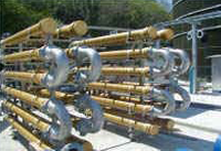
For the moment, we'll leave aside nanofiltration and reverse osmosis, as this classification is actually based on the nominal pore size or diameter, e.g., between 0.06 and 2 µm for microfiltration, between 0.005 and 0.1 µm for ultrafiltration, between 0.001 and 0.01 µm, and finally between 0.0001 and 0.002 µm for reverse osmosis. Similar to bag filters used for particulate separation in gas treatment projects, the gradual deposition of material onto the support, e.g., filter cloth or membrane, effectively reduces the effective retention diameter, thus trapping smaller particles.
Analogous to the aforementioned air application, the pressure drop will gradually increase until it reaches the cutoff level, inducing a type of (self-)cleaning. In the case of wastewater treatment, we actually have a synergy or hybrid system formed by the synthetic material (membrane) and the bio-gel or film (biomass, proteins), a biological component that, in this context, blurs the distinction between microfiltration and ultrafiltration. In fact, very similar results can be observed when comparing the two alternatives in the field.
Within the context of wastewater treatment plants, biomembrane systems, primarily as an alternative to microfiltration, have found two major fields of application, namely:
1. assume the functions classically assigned to granular filters, i.e., removal of turbidity, suspended solids, parasites, and most of the bacteria present in the effluent from the secondary sedimentation tank, and additionally
2. assume the functions of the secondary sedimenter, in which case the membrane assembly is either submerged (permanently in the tank itself, in the nitrification zone or in a separate partition) or installed out of the water.
Even with the remarkable evolution of membranes, both in terms of cost and new materials and design, the general consensus regarding their use seems to be that they are the best alternative for pretreatment in reverse osmosis processes. While the idea of using membranes in wastewater treatment plants was developed by Dorr Oliver in the 1960s for municipal facilities, some of the difficulties encountered then have not been overcome today.
Even though it is possible to work with much larger biomass inventories, e.g., MLSS three or four times the conventional rate, the energy requirements are greater and force diffused aeration systems to operate at their worst, i.e., 40-50 lbBOD/day per 1,000 cu.ft. Typically, cautious diffuse aeration designs, by promoting food-to-mass ratios (of/m), "automatically" implied working with conservative volumetric organic loading rates, i.e., 10–15 lbBOD/day per 1,000 cu.ft. Hopefully, the entire new generation of systems will not forget the negative experiences prior to membranes.
We recommend rereading the information presented elsewhere , especially the oxygen transfer curves, even in clean water, as power density increases, i.e., 100–500 HP per megagallon of tank.
Finally, it may be important to ensure a responsible characterization of the effluent as well as adherence to the macro guidelines of the basic design, e.g., favoring low-rate processes, considering TKN in oxygen forecasting, P treatment, maintaining adequate levels of complete mixing through correct power density, balanced nutrient supplementation, uniform hydraulic and organic feed (equalizers), pre-removal of oily/greasy material, generous sludge residence times and age, among other aspects. While membranes fulfill the dual function of retaining biomass and polishing the effluent, the essential element is to promote the biological process.
In a way, there is a contrast between the simplicity of the concept—essentially the physical separation of different components within the liquid—and its successful implementation. As mentioned, it is a simple particulate separation mechanism, ultimately summarized in the use of a permeable or porous capillary tube, fed either internally by pressure or externally by vacuum suction.
Perhaps the quickest or most agile way to explain the operating principle is by using the following expression:
flux = k * D p = D p / (µ * R)
being:
D p = pressure difference across the membrane (TMP)
µ = viscosity of water
R = membrane resistance
This helps explain the operation of the two most common configurations: an immersed membrane, where pumping is induced by a slight vacuum and can even be maintained by a siphon effect, and an external, pressurized membrane operating at higher flow densities. We can now begin to understand the importance of liquid temperature in ensuring that operating conditions match design specifications.
Naturally, there is a wide variety of construction materials, and typically some type of sandwich structure, i.e., a combination of a filter element with a support or reinforcing material, e.g., polyethylene elements and an ABS support. Other materials used include polypropylene, cellulose acetate, PVDF, PES/PCP, PAN, and PVC, among others.
It is interesting to note that the characteristics of the biomass inventory in biomembrane systems are different from conventional processes, e.g. smaller and more dispersed flocs, lower settleability, a greater number of free-swimming organisms, and few ciliates or filamentous organisms.
It's not easy for a consulting firm to design an MBR system. Although MBR membrane modules are available commercially, there are a lot of associated factors that deal with chemical compatibility of wastewater constituents with the membrane material, appropriate mixed liquor solids concentrations, membrane fouling, cleaning methods, etc. that must be addressed in first deciding to use MBRs and second selecting the correct type and size of membrane modules. It also is almost impossible to operated a lab-scale MBR for sufficient time and under the field-scale range of operation to identify the factors associated with membrane selection. For example, fouling can develop over the first year of two, so to simulate field conditions, the lab-scale MBR would need to be operated for this length of time. Companies such as ADI, Paques, Biothane, Xylem, GE etc. have spent millions on researching these factors.
Most membrane companies or MBR supplies will have pilot-scale membrane modules. It is recommended to design the system for side-stream membrane operation rather than in-basin modules so that you can control the membrane type and size easier, but in-basin modules -- like Kubota's -- make a simpler system without transfer pumps. A system this size likely means that you will need at least one full-time operator and associated capabilities for sampling and analysis.
We run lab-scale MBR pilots in the lab using 1 L reactors and filter the effluent through 0.2 um filters to simulate MBR performance. To run a true continuous-flow MBR pilot in the lab would require continuous feed with a lab scale MBR unit with pump and backwash mechanism. To simulate pressure drops and fouling, the pilot would need to be run at least three months.
The three most common MBR types are:
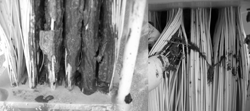
Hollow Fiber (HF): use narrow, tubular fibers typically immersed vertically in the activated sludge tank. They are commonly used in full-scale MBR systems.
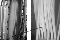
Flat Sheet (FS): use flat, rectangular sheets, arranged in cassettes or packs, and also operate submerged in the aeration tank. Often favored for easier installation.
Multitube or Multichannel (MT/MC): use cylindrical tubular membranes housed in external units also called sidestream MBR systems.
The most popular submerged type aeration systems include diffused aeration systems and submerged, turbine-type aeration and mixing aerator configurations.
Diffused aeration systems are frequently classified into two major categories according to the diffuser's pore/bubble size, i.e. fine-pore diffusers and medium/coarse diffusers.
Medium/coarse diffused aeration systems are used in foul-prone applications.
Both fine and coarse bubble diffusers can be used in retrievable racks/arrangements, diffuser banks or assemblies either sitting on basin bottoms or evenly suspended to overcome irregular, lagoon-type floors.
Submerged jet aerators, i.e. basically a pump and submerged venturi-type diffuser, call for 8 to 10 m deep water levels. In this type of system, mixing and air supply can be operated independently of each other, i.e. pump only or pump and controlled introduction of pressurized air.
Most types and brands are suitable for AS applications, but each has its own best applications. For example, brush aerators are best for oxidation ditches while fixed diffusers and surface aerators are best for conventional AS systems. The key is to size the unit properly for each application. Once OTR characteristics are established, the sizing is fairly straightforward. Other factors include alpha factor, impact of floc size and settleability, impact on effluent TSS, etc. The key phrase is "if properly sized/selected."
For conventional activated sludge of average rate, i.e. medium rate, it is generally recommended approximately 50 lbBOD/1,000 cu.ft. as maximum. For process stability and better assurances of performance, [fine pore/fine bubble] diffused aeration systems favor the use of low f/m and that is generally restricted to about 10-15 lbBOD/1,000 cu.ft. This significantly lower rate sizing tip takes into account process recommendations (extended aeration) as well as diffuser technology old hands recommendations.
Design of the aeration
tanks is also important for optimum efficiency. Proper tank design can make it or break it for any given aeration system selection. It is often the case that the same identical piece of equipment or given amount of hardware will deliver far more return for the investment if only careful/generous process considerations are taken into account, adding buffer treatment capacity.
For best performance, mechanical surface aerator vendors frequently suggest recommended/minimum/maximum liquid depths for their standard units. If basin is too deep, the aerator may not be able to effectively pump up beyond a given depth thus resulting in idle pockets or even whole layers, at least as regards intended aerobic activity.
Fine bubble diffusers
can work at 2.5m water depth but deeper basins will give greater efficiency
and superior results on capital costs. Diffusers are directly
dependent on liquid depth for their aggregate efficiency. As a result,
if the basin depth is doubled, it will approximately use the same horsepower
but it will take only roughly one-half the number of required diffusers,
i.e. capital cost of the diffusers is about 50%. Using deeper basins,
e.g. 5m, and larger volumes offer much better assurances of performance.
It must be said that one of the authors once witnessed a probably still
existing wastewater treatment plant at an edible oil plant having a
detention time of ... [only] ten (10) minutes.
Mike Tate, P.E. Activated Sludge, Oxidation Ditches, SBRs and more
Sample keywords: hydrogen sulfide EGSB tannery (no commas!)


