


 |
Evaporative Condensers Need to know more? Send us an email or feel free to search our online series with our give away search engine: |
 |
Evaporative condenser basic design and performance can be numerically examined using Newton's equation.
Q = U * A * LMTD
where
Q = heat reject, btu/hr
U = transfer coefficient
A = surface area, e.g. st.ft.
LMTD = mean logarithmic temperature
Let's work out an hypothetical design for an ammonia evaporative condenser using said formula using U = 100, and a common condensing pressure target.
| Ammonia Condenser Sizing | |||||||
| Q | 756049 | kca/h | 3000002 | btu/h | 880 | kW | |
| Twb | 25 | °C | 77.0 | °F | |||
| Tcondensing | 35.72 | °C | 96.3 | °F | |||
| chiller tons | 200.0 | tons (15k) | 250 | tons (12k) | IF at 2.1 U.S. GPM per chiller ton | ||
| water flow | 600.0 | U.S. GPM at 3 GPM per chiller ton | 486.0 | U.S. GPM at 2.43 | |||
| 37.9 | lps | 30.7 | lps | ||||
| face area sq.ft. | 100.0 | sq.ft. at 6 gpm/sq.ft. | 81.0 | sq.ft. | area (alt.) | ||
| tentative air flow | 60000.0 | CFM at typ. 600 fpm | 48600.0 | CFM (alt.) | |||
| l/g = | 1.2 | ||||||
| delta enthalpy | 11.7 | btu/lb | |||||
| Hin | 45.0 | btu/lb | |||||
| Hout = Hin + delta | 56.7 | btu/lb | |||||
| saturated air out at | 88.7 | °F | |||||
| LMTD | 12.6 | °F | 7.0 | °C | |||
| U | 100 | cu.ft. 3/4" coil | |||||
| required area | 2388.4 | sq.ft. | 222.0 | m2 | 2388.4 | sq.ft. | 37.3 |
| + 20% safety factor | 2866.0 | sq.ft. | 266.4 | m2 | 2866.0 | sq.ft. | 44.8 |
| condenser Q | thickness | Thermal DeRating | % Capacity | ||||
| Original Capacity | 756049 | kcal/h | 0 | 200 | chiller tons | 100 | |
| 0.8mm scale | 551916 | kcal/h | 0.8 | 146 | chiller tons | 73 | |
| 1.0mm scale | 415827 | kcal/h | 1 | 110 | chiller tons | 55 | |
| 2.0mm scale | 287299 | kcal/h | 2 | 76 | chiller tons | 38 | |
| 2.0mm & recirculation | 244204 | kcal/h | 65 | chiller tons | 32 | ||

This unassuming graph unfortunately accurately depicts what one can frequently see in actual plants and real world reports:
"Evaporative condensing is still by far the most economical means to remove latent heat. However, this holds true as long as the heat transfer surfaces on both sides of the tubes are kept clean and free of thermal insulating films such as oil, scale, algae growth." (James Dodds - Argentina/Brazil/USA; manufacturer; awarded United States Patent 4,693,302).
"Because of these problems, the potential for lower capital and operating costs from evaporative condensers may not be realizeddue to poor design, poor installation or poor operating practices." (Brake, Australia)
You should pay extreme attention to water treatment of the condensers [evaporative], as this aspect is one of the vulnerabilities of these condensers [evaporative]. If water is not properly treated it will lead to rapid deposition of salts of calcium and magnesium on the surface of the exchanger, thereby significantly reducing the transfer and the efficiency of the condenser, canceling advantages over other types of condensers. "(Wong et al., Cuba)
We feel that installing twice the required EC capacity may not be a commendable path to pursue. Probably more energy would be saved/generated in the industrial refrigeration field alone (versus wind, solar, other) by sticking to said subject fundamentals (low HPs everywhere) and simply selecting instead easy to maintain cooling tower and shell and tube condensers, matching condensing targets with lower HPs as well. In many locales, actual EC practice (energy savings not a priority) runs against the true evaporative cooling/condenser rationale. Machines cannot be more efficient than the standard set by installers and vendors
EXAMPLE Within its pasteurization circuit, a dairy industry must cool approximately 50,000 gallons of milk (c. 190 m3/h) from 75°F (23.9°C) to 40°F (4.4°C) in three (3) hours. An estimate of the process heat is desired, along with outlining possible alternative operating regimes, but in all cases limiting the pasteurizer's operation to only three (3) hours.
The pasteurization process , whether for milk, beer, pulps, or creams, offers an excellent framework for illustrating this situation due to its dual perspective of cooling and refrigeration working in tandem, a combination that is both thermally instructive and common. Typically, the product is heated to a temperature of, say, 140°F (60°C) for 30 minutes, after which it is cooled in a first stage with cooling tower water to, say, 80°F (27°C), and then in a second stage to a product temperature of around 40°F (4.4°C) using mechanical refrigeration. This configuration illustrates the best possible synergy: the cooling tower performs a first stage of significant thermal "reduction" to minimize all associated costs of the second stage, including both equipment size and energy consumption. This combined cooling tower/mechanical refrigeration configuration is a classic workhorse of the industry.
Assuming a specific heat of 0.95 and a specific gravity of 1.032 (4% fat), the heat to be extracted, using conversion factors, is
Q (btu/h) + 50,000 * 8.33 * 1.032 * 0.95 * (75 - 40) = 14,291,781 btu/h.
Adding 10% to anticipate losses and/or leaks, the estimated heat absorbed in the process is
Q (btu/h) = 14,291,781 btu/h * 1.1 = 15,720,960 btu/h.
If equipment were selected that would only operate for the same duration as the limit imposed by the pasteurizer's operation, that is, only three hours, the capacity of the appropriate compressor should be on the order of
Q (tons) = 15,720,960 btu/h / (3 hours * 12,000 btu/h tons) = 437 tons (cooling effect)
If it were possible to use some type of accumulator, whether a pre-cooled water reservoir or an ice bank, one could consider a refrigeration unit that operates, say, 10 hours per day. In this case, the capacity of the appropriate compressor would be
Q (tons) = 15,720,960 btu/h / (10 hours * 12,000 btu/h tons) = 131 tons (cooling effect)
It will be important to carefully consider the pros and cons (advantages and disadvantages, or energy balances) of the two distinctly well-defined refrigeration scenarios: a configuration involving suction temperatures of, say, -10°C for the ice bank alternative versus simply producing chilled water at 1 or 2°C. Interestingly, a number of ice bank proponents simultaneously promote evaporative condensers, both of which are tube bundle designs. With the current availability and notable improvements in both refrigeration equipment and heat exchangers of all types, including increasingly stainless steel heat exchangers, we are witnessing a considerable historical technical review in the field and a return, in industrial refrigeration contexts , to the classic and proven configurations based on condensers and water cooling towers versus the highly questionable alternative of evaporative condensers ( direct evaporation on tubes, resulting in a 45% loss of heat exchange with just 1mm of scale).
The conclusion is immediately clear: it is highly advisable to seek the highest possible qualifications and expertise for any installation, regardless of size, due to the numerous nuances that must be examined on a case-by-case basis. It is obvious that there are genuine opportunities for added value and the incorporation of real "structural/perpetual" production savings that will be, for better or worse, consolidated for the entire operating cycle of the installation. After that, no frequency inverter, automation system, or alternative energy source will undo the damage. A good example of the intangible value of a process is cooling, refrigeration, or central air conditioning.
EXAMPLE: A small refrigeration plant wishes to determine the necessary heat exchange area in condensers to serve the machinery fleet in the context of operation as detailed
| Capacity Planning | |||||||||||
| Current machinery fleet | |||||||||||
| kcal/hr | chiller tons | HP (nominal) o BHP | Q heat reject (chiller tons * 12,000 + HP * 2545) | ||||||||
| Howden a screw (machine #9) | 675000 | 178.6 | 300 | 2906220 | btu/h | ||||||
| reciprocating machine (machine #8) | 140000 | 37.0 | 100 | 698916 | btu/h | ||||||
| Howden a screw (machine #1) | 340000 | 89.9 | 125 | 1397421 | btu/h | ||||||
| Howden a screw (machine #2) | 340000 | 89.9 | 125 | 1397421 | btu/h | ||||||
| mycom reciprocating (machine #4) | 300000 | 79.4 | 150 | 1334070 | btu/h | ||||||
| reciprocating madef (machine #3) | 276000 | 73.0 | 150 | 1257884 | btu/h | ||||||
| Howden a screw (machine #5) | 420000 | 111.1 | 250 | 1969498 | btu/h | ||||||
| Howden a screw (machine #6) | 420000 | 111.1 | 250 | 1969498 | btu/h | ||||||
| reciprocating madef (machine #7) | 92000 | 24.3 | 40 | 393844.8 | btu/h | ||||||
| Howden Booster (Machine #10) | 400000 | 105.8 | 200 | 1778760 | btu/h | ||||||
| 900.2 | 15103533 | btu/h | 3806334 | kcal/h | |||||||
| Heat dissipation characteristics in the case of shell and tube type capacitors | |||||||||||
| Assuming a recommended condensation temperature of 35°C (95°F) | |||||||||||
| Heat exchanger literature recommends temperature t1 = tc - 5°F = 95 - 5 = 90°F | |||||||||||
| Assuming a preliminary temperature jump of 7.5°F, the following context applies to the capacitors | |||||||||||
| water inlet | 82.5 | °F | 28.1 | ° Celsius | |||||||
| water outlet | 90.0 | °F | 32.2 | ° Celsius | |||||||
| condensation | 95.0 | °F | 35.0 | ° Celsius | |||||||
| The following LMTDs result: | |||||||||||
| IP units | LMTD = | 8.185 | |||||||||
| SI units | LMTD = | 4.547 | |||||||||
| flow rate in the case of shell and tube condensers, using Q = gpm * 500 * range | |||||||||||
| gpm = | 4027.6 | U.S. GPM | |||||||||
| IP | SI units | ||||||||||
| Estimation of exchange area using the formula Q = U * LMTD * surface area | U = | 200 | 976 | ||||||||
| surface area (sq.ft.) = | 9226.3 | sq.ft. = | 857.5 | m2 | |||||||
| verification | |||||||||||
| surface area (m2) = | 857.7 | m2 (approx.) | |||||||||
If central air conditioning and industrial refrigeration systems operated according to the best practice guidelines that gave rise to the various specializations—specifically, by keeping target and actual condensing temperatures as low as possible—the energy saved would be greater than that potentially produced by any of the alternative energy sources currently being considered. We have not found a single person, whether from the industrial, HVAC, or institutional sectors, who denies our assertion!
Similar to the capacity planning illustrated for central air conditioning installations, it is possible to establish comparative operating charts, especially considering that the industrial refrigeration installation is typically in service 365/7/24, as is probably the case with most industrial installations.
Whether the installation is "large" or "small," the impact of penalties/excessive consumption, translated into annual costs in the tens or hundreds of thousands of dollars, is quite significant. The following table illustrates the financial losses incurred by the user.
| INSTALLATION A | |||||||||
| Condensation Temperature | 105 | °F | 40.6 | °C | 1.58 | BHP/ton | (15 kg/cm2) | ||
| Cooling Effect | 1200 | tons | (in evaporation) | 1896 | HPs | 1415 | kW | (214 psig) | |
| usd/kW h | |||||||||
| 365 | 24 | 12394746 | kWh | 0.2 | 2478949 | u$s/year | |||
| Condensation Temperature | 95 | °F | 35 | °C | 1.37 | BHP/ton | (12.7 kg/cm2) | ||
| Cooling Effect | 1200 | tons | 1644 | HPs | 1227 | kW | (181 psig) | ||
| usd/kW h | |||||||||
| 365 | 24 | 10747343 | kWh | 0.2 | 2149469 | u$s/year | |||
| Penalty | 329481 | u$s/year | |||||||
| INSTALLATION B | |||||||||
| Condensation Temperature | 105 | °F | 40.6 | °C | 1.58 | BHP/ton | (15 kg/cm2) | ||
| Cooling Effect | 220 | tons | 347.6 | HPs | 259 | kW | (214 psig) | ||
| usd/kW h | |||||||||
| 365 | 24 | 2272370 | kWh | 0.2 | 454474 | u$s/year | |||
| Condensation Temperature | 95 | °F | 35 | °C | 1.37 | BHP/ton | (12.7 kg/cm2) | ||
| Cooling Effect | 220 | tons | 301.4 | HPs | 225 | kW | (181 psig) | ||
| usd/kW h | |||||||||
| 365 | 24 | 1970346 | kWh | 0.2 | 394069 | u$s/year | |||
| Penalty | 60405 | u$s/year | |||||||
The harm passed on to the user is several times any amount of honest supply/investment!
Fortunately, today it's possible to carry out capacity planning for any industrial refrigeration system , eliminating or at least reducing these daunting hidden costs. To the classic industry recommendation—that is, to operate with the lowest possible condensing temperatures/pressures—we can add the unequivocal recommendation of the extremely simple conversion/migration of existing evaporative condensers to condenser configurations (e.g., case and tube) and cooling towers.
Fortunately, today it's possible to carry out capacity planning for any industrial refrigeration system , eliminating or at least reducing these daunting hidden costs. To the classic industry recommendation—that is, to operate with the lowest possible condensing temperatures/pressures—we can add the unequivocal recommendation of the extremely simple conversion/migration of existing evaporative condensers to condenser configurations (e.g., case and tube) and cooling towers.
Besides numerous other drawbacks, the CAPACITY PLANNING OF AN EVAPORATIVE CONDENSER reveals the terrible THERMAL COLLAPSE that occurs shortly after installation due to the increased thickness of the scale film ( direct evaporation on the tubes, similar to a low-pressure boiler). As grim as it is graphic:
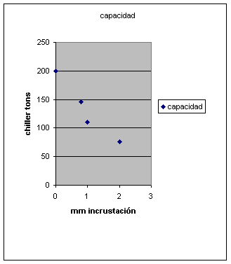
Here is the detailed calculation, which is conclusive (Technical note: it is Newton with the design coefficients of the original manufacturers ).
| EC Sizer B&B/CTI S.A. | |||||||||
| Q | 756049 | kcal/h | 3000002 | btu/h | 880 | kW | |||
| Already | 25 | °C | 77.0 | °F | C-1766 | ||||
| Tcondensing | 35.72 | °C | 96.3 | °F | 1/10/13 | ||||
| chiller tons | 200.0 | tons (15k) | 250 | tons (12k) | IF at 2.1 U.S. GPM per chiller ton | ||||
| water flow | 600.0 | U.S. GPM at 3 GPM per chiller ton | 486.0 | U.S. GPM at 2.43 | |||||
| 37.9 | lps | 30.7 | lps | ||||||
| face area sq.ft. | 100.0 | sq.ft. at 6 gpm/sq.ft. | 81.0 | sq.ft. | area (alt.) | ||||
| tentative air flow | 60000.0 | CFM at typ. 600 fpm | 101941 | m3/h | 48600.0 | CFM (alt.) | |||
| l/g = | 1.2 | ||||||||
| delta enthalpy | 11.7 | btu/lb | Evaporative Condenser Calculation (R-717) | ||||||
| CAPACITY COLLAPSE | |||||||||
| Don't | 45.0 | btu/lb | |||||||
| Wood = Hin + delta | 56.7 | btu/lb | |||||||
| Note the conservative value in the choice | |||||||||
| saturated air out at | 88.7 | °F | of the U design, classic within the | ||||||
| manufacturers of good schools. | |||||||||
| LMTD | 12.6 | °F | 7.0 | °C | |||||
| IN | 100 | cu.ft. 3/4" coil | |||||||
| required area | 2388.4 | sq.ft. | 222.0 | m2 | 2388.4 | sq.ft. | 37.3 | ||
| + 20% safety factor | 2866.0 | sq.ft. | 266.4 | m2 | 2866.0 | sq.ft. | 44.8 | ||
| Q capacitor | thickness mm | Cooling Effect | % ability | ||||||
| Original Capacity | 756049 | kcal/h | 0 | 200 | chiller tons | 100 | |||
| Capacity 0.8mm | 551916 | kcal/h | 0.8 | 146 | chiller tons | 73 | |||
| Capacity 1mm | 415827 | kcal/h | 1 | 110 | chiller tons | 55 | |||
| Capacity 2mm | 287299 | kcal/h | 2 | 76 | chiller tons | 38 | |||
| Capacity 2mm & re. | 244204 | kcal/h | 65 | chiller tons | 32 | ||||
The harm passed on to the user is several times any amount of honest supply/investment!
Sample keywords: hydrogen sulfide EGSB tannery (no commas!)
