


 |
Evaporative Condensers Need to know more? Send us an email or feel free to search our online series with our give away search engine: |
 |
Evaporative condenser basic design and performance can be numerically examined using Newton's equation.
Q = U * A * LMTD
where
Q = heat reject, btu/hr
U = transfer coefficient
A = surface area, e.g. st.ft.
LMTD = mean logarithmic temperature
In our experience, this formula has proved successful enough in terms of interpretation of unit specifications, as supplied by each particular manufacturer. Unfortunately, not all industrial equipment suppliers choose to openly publish their specifications and actual performance data. Vendor catalogs and many engineering proposals often contain "inaccuracies" only to be noticed once the under-performing equipment becomes operative. While the model represents a significant simplification (basically assumes an air behavior following the saturation line, starting from a specific wet-bulb temperature and condensing temperature) it closely matches most available trade literature.
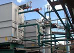 Standard evaporative condensers, unlike cooling towers, are almost always selected/ designed/built with liquid-to-gas (L/G) ratios typically hovering 1.1 - 1.2, which obviously considerably limits its optimization. Any cooling tower designer can work with ratios L / G ranging between 0.6 and 2.2, which greatly allows job optimization and size to meet or accommodate a variety of criteria, e.g. lower fan HP, lower required area, direct drive fan restrictions. Selection by way of catalog further handicaps the final decision.
Blurred bid specifications only go against the future equipment owner. Calculation formulas and algorithms cannot be technically more honest than what participants are bent to install in reality no matter what.
An incorrect wet bulb selection results in an extremely, non-linear underperformance of the unit. An EC selected to dissipate a certain amount of heat in an area with a wet bulb temperature of say 75 ° F, will thermally collapse in locations with significantly higher prevailing wet bulb, 78-80 ° F.
The selection of the heat transfer coefficient U must take into account the "de-rating" caused by unfavorable conditions in the field. The consequences of ignoring this item, unintentionally or maliciously, will gravely short-change the trusting end user.
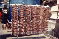 Most common EC enclosure is hot-dip galvanized steel. Tube material can be galvanized steel or copper or other material depending on the application/refrigerant. Most common water distribution materials include plastic pipe and nozzles. PVC drift eliminators are frequently the standard.
Like central air conditioning and thermal generation facilities, the condensation and evaporative cooling section is the Achilles' heel of industrial refrigeration.
Investments worth thousands and millions of dollars can be severely compromised or simply dysfunctional, in addition to the many times greater economic losses they cause to users. The undersizing of the condensation and evaporative cooling unit, whether intentional or unintentional, can easily result in installations with only a third of the agreed-upon or required condensation capacity.
Fortunately, virtually all industrial refrigeration technologies are widely known. It's almost as if those who don't know simply don't want to know! Today, it's extremely easy to predict the operation of a generic compressor—whether centrifugal, screw, rotary, or reciprocating—using polynomial approximations. Likewise, almost every major manufacturer offers selection programs and calculation/operation platforms with the desired level of detail, something unthinkable relatively recently. However, the advances in both technology and these notable possibilities for disseminating or accessing information don't always translate into the benefits agreed upon, promised, and expected by users. In a way, by performing simple capacity planning calculations for each step or stage, it's also extremely easy to anticipate the potential drawbacks of a given decision.
It will be important to discriminate between refrigeration or mechanical refrigeration, i.e., based on a specific refrigerant (ammonia, freons) achievable through a variety of equipment (compressors: screw, reciprocating, rotary) vs. what we will prefer to call cooling or evaporative cooling, equipment based on the intensive application of the natural phenomenon of evaporative cooling, commonly represented by units of the water cooling tower type, eventually in conjunction with conventional condensers of different types (e.g., shell and tube, plate) and evaporative condensers.
The heat to be dissipated required by a refrigeration machine can be approximated by the classic formula and its variants (open, closed, multi-stage systems) that involve the heat absorbed in the evaporator expressed in some way (e.g., refrigeration effect in chiller tons, i.e., 1 chiller ton = 12,000 btu/h) plus the power consumed or nominal of the compressor motor and, if desired, a safety margin according to the designer.
Thus, if, for example, a small wine industry specifies an installation of 69.3 tons of chiller cooling capacity and a BHP increased by the nominal value of the equipment (100 HP), the heat to be dissipated in the condensation sector will be given by:
Q = 69.3 tons * 12,000 btu/h per ton + 100 HP * 2545 btu/h per HP = 1,086,100 btu/h (1)
This fairly accurately reflects most industrial refrigeration contexts: "to achieve one ton of cooling effect we must 'pay' practically between 1.5 and 2 times the value expressed in HP."
In air conditioning systems, and potentially in refrigeration systems where information is lacking, the compressor's horsepower (HP) can be taken as an "indicator" of the cooling effect. While this isn't necessarily accurate in the latter case, for preliminary design purposes, specifically for sizing the condenser section, it at least provides a safe overestimate rather than a low estimate.
Whether an air conditioning contractor has requested equipment to work with a refrigeration unit of, say, 890 tons, or the person in charge of the cold storage facility has informed us, "Look, there are about 900 HP in compressors," we can initially estimate the heat to be dissipated in condensation as:
for the central air conditioning contractor
Q = 890 tons* 12,000 btu/h per ton + 890 HP * 2545 btu/h per HP = 12,945,050 btu/h (2)
and for the person in charge of the refrigerator
Q = 900tons * 12,000 btu/h per ton + 900 HP * 2545 btu/h per HP = 13,090,500 btu/h (3)
Now, while in expression (2) the approximation is quite correct, and frequently estimated by multiplying the cooling effect in tons by a factor of 15,000 btu/h per chiller ton (the second term is typically 25%), in expression (3) there is clearly an “overkill.”
Indeed, if we had approximated the wine industry example in this way, in the case where the value of the cooling effect had not been indicated, the heat to be dissipated, instead of what (1) indicates, would be given by
Q = 100tons * 12,000 btu/h per ton + 100 HP * 2545 btu/h per HP = 1,454,500 btu/h (4)
Comparing (1) and (4), we see that the latter approximation has a safety margin of 1.34x (=1454500/1086100). While in a small installation such oversizing may not be critical, it is obvious that in large installations, it is necessary to "fine-tune the design" for the benefit of all.
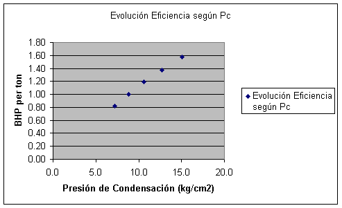
Excluding, of course, raising the operating suction temperature, which is permissible depending on load/demand and context, the general global recommendation/guideline is simply to operate with the lowest possible condensing pressures, keeping pace with the prevailing wet-bulb temperature. This central point, even to the point of extreme sensitivity for all manufacturers of evaporative cooling equipment since the beginning of the field, has only recently (see manuscripts and materials by George Briley, 2003) been rediscovered, and even then only partially. While considerable sophistication in industrial refrigeration is documented, it lacks the contemporary refinements in the area of evaporative cooling, which, as we have said, is the Achilles' heel of industrial refrigeration. If the refrigeration equipment is properly sized, it will operate with the classic/legendary benefits of the field. If the system is undersized or uses units with sub-efficiency (as can be seen in evaporative condensers and prefabricated fiberglass cooling towers with an efficiency rating of around 30%), the benefits will not materialize within the expected ranges for the industry, leading to exorbitant cost increases. What manager doesn't want to reduce costs? A poor choice, whether in industrial refrigeration or central air conditioning, cannot be remedied later by simply trying to compensate with solar panels for showers!
The following summary table, taken from George Briley's collection of technical notes, numerically illustrates the benefit of operating at the lowest possible condensation temperatures.
| R-717 (ammonia) | |||||||
| Tc (°F) | Tc (°C) | Psig | kg/cm2 | bhp/ton | |||
| 105 | 40.6 | 214 | 15.0 | 1.58 | |||
| 95 | 35.0 | 181 | 12.7 | 1.37 | |||
| 85 | 29.4 | 151 | 10.6 | 1.19 | |||
| 75 | 23.9 | 125 | 8.8 | 1.00 | |||
| 65 | 18.3 | 103 | 7.2 | 0.82 | |||
.
A small refrigeration facility wishes to synchronize available resources, i.e., three ammonia compressors, approximately 70 chiller tons each, three shell and tube condensers of 42.5 m² each, and two existing cooling cells, each of approximately 2.20m x 2.10m dimensions.
Although the person in charge of the refrigeration installation has detailed different operating contexts for the refrigeration equipment – see insert in PDF format – it has been estimated that in most cases, the daily operation of the plant will only require the operation of two of the compressors, each delivering 70 chiller tons (in the evaporator) and equipped with 100 HP motors. Therefore, the heat to be dissipated can be directly deduced:
Q = [70 tons * 12000 btu/h per ton + 100 HP * 2545 btu/h per HP] * 2 = 2189000 btu/h = 551664 kcal/h
It has been indicated that each existing shell and tube condenser offers approximately 42.5 m² of heat exchange surface area. Assuming all three are operational, the following heat exchange area will be available:
A = 3 * 42.5 m2 * 10.76 sq.ft. / m2 = 1371.9 sq.ft.
Since the installation is planned to operate with a condensing temperature of 95°F (35°C), it is proposed to receive cooling tower water at 82.5°F (28.06°C) and a condenser water outlet temperature of 90°F (32.22°C), resulting in the following LMTD:
LMTD = =((Tc-Ti)-(Tc-To))/LN((Tc-Ti)/(Tc-To)) = 8.185
Assuming the condensers operate at a conservative water velocity, we can consider values of U = 200 btu/h sq.ft. °F, so the heat they can exchange will be given, using Newton's equation, by:
Q = 1371.9 sq.ft. * 8.185 * 200 = 2245848 btu/h = 565990 kcal/h
Unless additional heat exchange surface is anticipated, in principle the cooling tower sector will simply need to be restored to handle the following flow rate:
Flow rate (US gpm) = Q / ( 500 * ( 90 – 82.5) = 2245848 / ( 500 * (90-82.5)) = ca. 600 US gpm
The survey of the existing structures, measuring 2.10m x 2.20m, indicates that a capacity of 1,372,884 BTU/h per cell, or 366.1 GPM at 90/82.5/twb°F (83,141 L/h at 32.22/28.06/twb°C), is easily achievable. Therefore, unless a capacity/plant expansion is planned in the short term, retrofitting the existing units will suffice.
Sample keywords: hydrogen sulfide EGSB tannery (no commas!)
