


 |
Evaporative Condensers Need to know more? Send us an email or feel free to search our online series with our give away search engine: |
 |
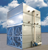 Evaporative condensers basically consist of some enclosure or shell housing a given amount of galvanized steel or copper coil. Water is doused all over the coil banks by nozzles. A fraction of the liquid evaporates removing latent heat released by refrigerant condensation. The remaining liquid flow keeps trickling down and is finally collected in some sort of bottom basin or sump and recirculated back to the top of the coil banks for another round. In properly designed evaporative condensers, the small fraction that evaporates during this brief passage is enough to achieve condensation targets. There is also a small sensible heat loss due to the temperature difference between incoming hot gas and air.
Evaporative condensers can be further classified as either induced or forced draft units. Induced draft units induce a negative pressure or vacuum right below the fan and pull in air from frequently louvered window sides. In forced draft units one or more fans are located at the air inlet as determined and essentially blow through required airflow. Forced draft condensers are usually made available with centrifugal as well as axial fan model configurations.
 Induced draft designs insure an even, smooth air distribution over the unit's cross-section and if properly designed, e.g. larger diameter fans, can significantly lower required fan HP for a given thermal context. Forced-draft units risk significant thermal de-rating due to recirculation. In order to avoid this, some unfortunate forced-draft designs operate at the upper "thru tube" velocities, say 675 - 700 fpm only to find themselves requiring twice or thrice fan HP to load duty comparable, more engineered induced draft units specifically designed to operate at much lower "thru tube" velocity and selecting larger fan diameters. Centrifugal fan units characteristically require twice as much power as the same thermal capacity axial fan models
The main focus of this technical digital iteration is the numerical energy analysis of evaporative condensers and cooling towers serving duty in specific operating contexts including industrial refrigeration, condensation, and related applications, including, to some extent, central air conditioning and thermal generation systems.
If users in these sectors were to adhere to the original operating frameworks for their respective specialties, they would likely save or redirect more energy than any of the conventional alternative energy generation methods currently available. We haven't encountered anyone in all (50) years who would deny this assertion! Furthermore, the negative impacts on end users can now be quantified relatively easily and translate annually, for example, into thousands upon thousands of dollars. These penalties, not immediately apparent but resulting in substantial cost expenditures, are largely avoidable. Essentially, it's a matter of rationalizing resources by using the classic operating guidelines and frameworks for each specialty, the very purpose for which the equipment was designed.
On the other hand, with the contemporary availability and notable improvements in both refrigeration equipment and heat exchangers of all types, including heat exchangers increasingly supplied in stainless steel, we are witnessing a considerable historical technical revisionism in the specialty and the return in industrial refrigeration contexts of the classic and proven configurations based on condensers and water cooling towers versus the highly questionable alternative of evaporative condensers ( direct evaporation on tubes, collapse of around 45% of the heat exchange with barely 1mm of scaling)
Today, it is extremely easy to carry out capacity planning using spreadsheets. This planning can be applied in specific work contexts, such as, but not limited to, the following:
- industrial refrigeration capacity planning, examining the condensing block and evaporative cooling units in detail;
- steam condensation/heat generation capacity planning , examining the condenser bank and the corresponding cooling circuit;
- central HVAC capacity planning
The possible optimizations generally boil down to simply working with the lowest possible condensing pressures (e.g. Briley, multiple others), impeccable maintenance of generous heat exchange surfaces (e.g., Dodds), operating in contexts with the lowest possible target cold water temperature considering the wet-bulb temperature variation profiles (e.g., Burger), and appropriate sizing of the evaporative cooling block, among other things, with capacities as agreed upon and equipment design respecting global standards, including, for example, fan area-to-cell area ratios no less than, say, 40%. We typically receive inquiries from all over the world to verify, through calculations, the actual capacities of the various units. Nowadays, virtually every calculation step is carried out using spreadsheets or calculation programs specific to each discipline.
It is impossible to mention all the people who have helped us over the years and who make it possible for us to share their guidance today. After so much time, we are happy to express our special gratitude to Jim Dodds, PE , and Frank Spencer, P.E.. Reading George Briley's material on the various applications is particularly highly recommended.
We hope that this aeternally work-in-process primer will provide genuine assistance to industrial users and field professionals, as well as staff at research centers, specialists, technology laboratories, universities, and related institutions.
Sample keywords: hydrogen sulfide EGSB tannery (no commas!)
