INDUSTRIAL GAS FILTER APPLICATIONS
Application 1: Mining industry cyclone separator
A mining company wishes to review the operation of a series of cyclone separators whose characteristics are as follows:
Gas flow to process 1800 CFM
Particle diameter 5 µ
Intake window width A = 15.2 cm (0.5')
number of turns of the gas inside the cyclone N = 5
inlet/admission speed Vc = 18.3 m/s (60 fps)
For the purposes of the calculation, the following characteristics have been reasonably assumed:
solid/particle density 2000 kg/m3
gas viscosity 0.018 cp
gas density 1.2 kg/m3
The goal is to plot the capture efficiency curve vs. particle diameter.
Basically, it involves calculating the cutting diameter and then calculating the capture efficiency for each diameter of interest, graphing the results.
In our case, the direct evaluation of the formula already presented:
dc = cutting diameter = ((9*Width*Viscosity/(2*3.1415*N*Vc*DensityP))^0.5/3.28)*10^6
dc = (9 * 0.5' * 1.209^-5 lb/ft .s / (2.3 * 3.1415 * 5 * 60 fps * 124.8 lb/cu.ft.))^0.5/3.28)*10^6 = 4.6 µ
The rest of the calculation is reduced to a mere graph of efficiency vs. different diameters.
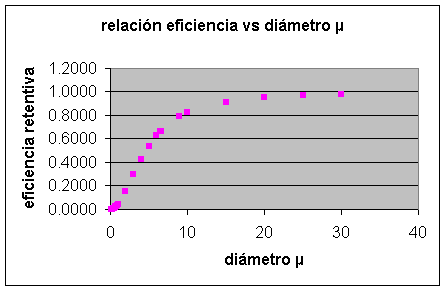
To see the calculation details, download the insert.
Application 2: Portland cement industry bag filter
A cement industry wishes to estimate the dimensions of a pulse-type bag filter, with the following specifications being applicable:
Gas flow to process 50,000 CFM
Particle diameter 7 µ
Particulate load 4 gr/cu.ft. (c. 9.2 g/m3)
Gas temperature 135°C (275°F)
Taking A = 9 to characterize the type of industrial particulate matter and B = 0.8 to penalize the application as a process (vs. simple venting), it is a direct evaluation of the formula already discussed:
V = 2.878 * A * B * T^-0.2335 * L^-0.06021 * (0.7471+0.0853 Ln D)
V = 2.878 * 9 * 0.8 * 275°F^-0.2335 * 4 gr/cu.ft.^-0.06021 * (0.7471+0.0853 Ln 7µ) = 4.69 fpm
The sleeve area is then:
50000 CFM / 4.60 fpm = 10660 sq.ft. = ca. 991 m2
Assuming a pressure drop of 12 inches of water column, the sizing of the associated fan would be as follows:
BHP = 50000 CFM * 12” * 0.000181 = 108.6 kW = ca.146 HP
Download the insert, which includes for comparative/illustrative purposes the details of the calculation including results associated with other types of particulates, in order to visualize the importance of the characterization of the gas phase.
Application 3: Venturi scrubber agro-industry
An agribusiness industry has approximately 400 tons/day of agroindustrial waste that it intends to recover as biomass for fuel. Among the alternatives being considered, the use of venturi-type scrubber towers is being explored for gas cleaning, with the following specifications being applicable.
Gas flow to process 200 m3/h
Particle diameter 8 µ
Gas temperature 100°C (212°F)
NOTE: Although no additional information is available, it is estimated that a general estimate can be made by showing capture percentages based on particle diameter, amount of water needed (available at 30°C) and order of magnitude in terms of energy requirements.
Certainly, a small numerical marathon recommends the use of a spreadsheet to minimize errors as well as to speculate on different scenarios – extremely didactic.
In any case, we can develop a "manual" sequence as follows:
Cunningham correction factor = 1 + (6.21/10^4) * T / df
being
T = temperature in °K
Df = particle diameter (physical)
In our case:
Cc = 1+(6.21/10^4)* (100°C+273) / 8 = 1.029
Based on the calculated correction factor, we can then estimate the aerodynamic diameter as follows
Aerodynamic diameter = Df*(Cc* r )^0.5
Where r = density of the particulate constituent, e.g. 1.7 g/cm3
In our case:
Aerodynamic diameter = Da = 8 µ * ( 1.029 * 1.7 g/cm3)^0.5 = 10.6 µ
Assuming a venturi velocity of Vv = 349 fps (= 10625 cm/s) and a liquid/gas ratio L/G = 0.0009, we can estimate the idealized droplet diameter according to the Nukiyama Tanasawa equation, namely
Drop diameter = Dg = 50/Vv +91.8*(L/G)^1.5 = 50 / 10625 cm/s + 91.8 * 0.0009^1.5 = 0.0072 cm = 72 µ
Assuming a gas-phase viscosity Vfg = 2 * 10^-4 g/cm s, we can now estimate the so-called inertial parameter Kpg , defined as
Kpg = Da^2 * Vv / ( 9 * Vfg * Dg) = (0.00106)^2 * 10625 cm/s / ( 9 * 0.0002 * .0072) = ca. 921
The Reynolds number is calculated directly, assuming for example a kinetic viscosity Vc = 0.2 cm2 /s, then we obtain:
Reynolds number = Nr = Vv * Dg / Vc = 10625 cm/s * .0072 cm / 0.2 cm2/s = 382
From the Reynolds number, we now calculate the resistance coefficient Cd :
Cd = =0.22+24*(1+0.15*Nr^0.6)/ Nr = =0.22+24*(1+0.15*382^0.6)/382 = 0.617
Finally, the parameter B , which characterizes the liquid-gas ratio, defined as
B = ( L/G) * liquid density (water) / ( gas phase density * Cd)
In our case it turns out
B = 0.0009 * 1000 kg/m3 / (1 kg/m3 * 0.617) = 1.46
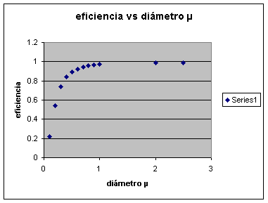
For the purposes of preliminary sizing, since we do not actually have data on the distribution, e.g., standard deviation, we evaluate the capture efficiency for the considered particle diameter, i.e., 8 µ, using the formula presented above:
capture efficiency = 1 – Pt
being
Pt = 1/ e^(B*(4*Kpg+4.2-5.02*Kpg^0.5*(1+0.7/Kpg)* ArcTan((Kpg/0.7)^0.5))/(Kpg+0.7))
Through arithmetic we obtain
Pt = 1/ e^(1.46*(4*921+4.2-5.02*921^0.5*(1+0.7/921)* ArcTan((921/0.7)^0.5))/(921+0.7)) = 0.0042
Finally
capture efficiency = 1 – Pt = 1 – 0.0042 = 0.9958
The venturi-type washing tower would be capturing approximately 99.58% of the 8 µ diameter particulate matter.
Repeating the exact same calculation sequence for other particle diameters yields the following graph of capture efficiency vs. particle diameter.
The pressure loss estimate comes directly
DeltaP = 8.24 * Vg^2 * L/G / 10^4 = 8.24 * (10625 cm/s)^2 * 0.0009 / 10^4= 84 cm ca = ca. 33” ca.
The energy required by each of the venturi-type washing towers will then be:
BHPs = 58799 CFM * 33” * 0.000181 = 351 kW = ca.470 HP order of magnitude
Download the insert , which illustrates the venturi calculation/behavior for particle diameters from 0.1 µm to practically 10 µm. You can also easily see how the BHP increases considerably when considering target efficiencies and the resulting higher pressure drop.
Application 4: Electrostatic precipitator
The required plate area for an electrostatic precipitator is to be estimated for a flow rate of approximately 1,700,000 m³/h (=1 * 10⁶ CFM), comparing approximations using the traditional formula, Deutsch-Andersen, versus a more conservative scenario using the Matts-Ohnfeldt variant with k = 0.5. The ash comes from a combustion process, 3 g/cu.ft (c. 7 g/m³) and a target outlet concentration of 0.02 g/cu.ft (46 mg/m³).
Based on the data, let's first calculate the required efficiency:
efficiency e = (3 – 0.02) / 3 = .9933 or 99.33%
Assuming a particle velocity of 0.3 fps
Deutsch Anderson
A = - Q*(LN(1-e))/(w*60) = =-10^6*(LN(1-0.9933))/(0.3fps *60) = 278092 sq.ft. = 25845 m2
Matts-Ohnfeldt
If k = 0.5
A = ( Q / ( w *60) ) * (-LN(1-e)) ^ (1/k) = ( 10^6 / (0.3 fps*60) ) * (-LN(1-0.9933)) ^ (1/0.5) = 1392028 sq.ft. = 129370 m2 = 5x the estimate by the historical formula
If k = 0.6
A = ( Q / ( w *60) ) * (-LN(1-e)) ^ (1/k) = ( 10^6 / (0.3 fps*60) ) * (-LN(1-0.9933)) ^ (1/0.5) = 815109 sq.ft. = 75754 m2 = 2.9x the estimate by the historical formula
The insert can be downloaded to view the results of the evaluation of both formulas for different approach speeds, e.g. 0.05 - 0.4 fps.
In order to obtain more information and/or request courtesy capacity plannings or case assessments, please send us an e-mail to answers@engineeringfundamentals.com cc.: balestie@umich.edu.
It is recommended to include a brief initial description of the case, ideally no more than one page, or project in progress / under study. The possibility of receiving and handling individual technical consultations has been foreseen but are limited as per availability. Alternatively make contact later on via sms/telephone +1 917 300 3024