VENTURI SCRUBBERS
Venturi-type scrubber towers allow for a high degree of particulate removal, even for smaller particle diameters, e.g., 2-3 µm, although with a consequent increase in energy requirements. For conceptual purposes, we can temporarily propose the following simplification to estimate the energy required for, say, 90% capture:
DeltaP (inches approx.) = 15” / diameter in µ
For example, retaining particles with a diameter of 0.5 µm would require approximately 30 inches. Obviously, in many cases, 90% removal is insufficient . To achieve 95% removal, operation should be around 60 inches.
In venturi-type gas scrubbers, the gas stream containing the particles is accelerated toward a central section, with either a variable or fixed flow rate , at which point the gas comes into contact with the cleaning fluid (which is simultaneously absorbent in the case of gas scrubbing, although the contact time is too short to provide a truly effective scrubbing alternative). Upon contact, the scrubbing fluid is finely atomized into droplets, e.g., 80–100 µm, which trap the particulate matter with high efficiency. As these droplets decelerate, they coalesce, forming larger formations that can be directed to the capture zone, either a settling section or, typically, a cyclone separator.
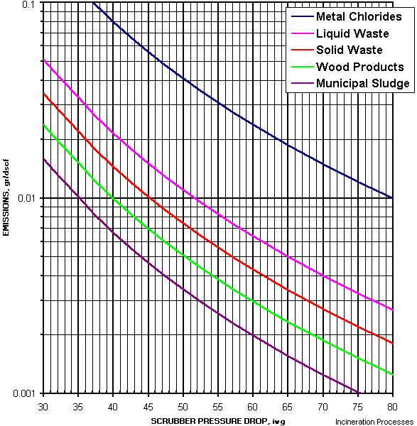
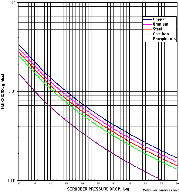
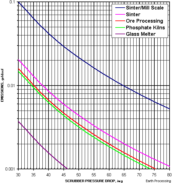
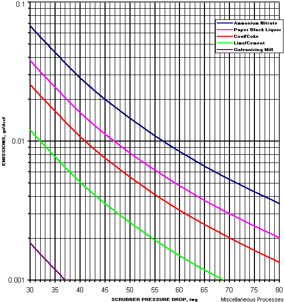
The pressure drop across the venturi passage is a measure of the energy required to perform the cleaning or capture operation. The greater the pressure drop, the greater the capture efficiency, but also the higher the BHP required to operate the system.
To accommodate extremely variable gas flow rates, variable opening orifices or variable passages can be used, although in general the use of fixed opening units is preferred, that is, those associated with a primarily uniform flow rate.
Among the advantages of venturi-type scrubber towers we can mention the relative compactness of the equipment, the possibility of purifying gas flows of adhesive particles, the absence of secondary particle problems in handling, and relatively low cost.
Among the disadvantages of venturi-type scrubber towers are the transfer of a gas-phase problem to a liquid-phase problem, i.e., the need to deal with the scrubber tower effluent; increased instances of corrosion; relatively high maintenance costs; accumulation of solids; generation of steam plumes; opacity problems; and product recovery under wet conditions, i.e., whether or not acceptable to plant operators.
Due to the short contact time offered by venturi scrubber towers, their application is primarily for particulate removal. While scrubbing of acid gases is possible, the efficiencies are generally too low, so a counter-current scrubber tower is often installed downstream, thus solving the dual problem of high acid gas removal and low particulate removal. In a few cases, a tandem of venturi scrubber towers (two units in series) may be specified, likely with the aid of additional injection, such as steam.
The sizing of a venturi-type washing tower can be acceptably carried out by the following step-by-step procedure, developed by the joint effort of Yung, Calvert et al ., and ideally assisted by some type of spreadsheet:
-
Cunningham correction factor calculation
-
aerodynamic diameter calculation
-
calculation of idealized droplet diameter
-
calculation of inertial parameter Kpg
-
calculation of the Reynolds number
-
Calculation of the resistance coefficient Cd
-
calculation of parameter B
-
efficiency calculation = 1 – Pt
Being
Pt = 1/ e^(B*(4*Kpg+4.2-5.02*Kpg^0.5*(1+0.7/Kpg)* ArcTan((Kpg/0.7)^0.5))/(Kpg+0.7))
Repeated use of the above sequence for different particle diameters allows for the plotting of removal/efficiency curves, as shown below.

This model, called the infinite step model , has been shown to have a very good correlation with operating data of full-scale venturi-type washing units.
Fortunately, it is also possible to obtain a good approximation of the associated pressure drop . While we include several formulas below for estimating pressure drop, we will develop step-by-step illustrations for the case of an agricultural industry in the Applications section .
DeltaP = 8.24 * Vg^2 * L/G / 10^4 (SI)
DeltaP = 4.0 * Vg^2 * L/G / 10^5 (IP)
DeltaP = Vg^2 * RoL * QL / Qg
For the purpose of verifying the calculations, we can compare any result with a known baseline, e.g., the estimated energy required for, say, 90% capture, using the following simplification:
DeltaP (inches approx.) = 15” / diameter in µ
For example, retaining particles with a diameter of 0.5 µm would require approximately 30 inches of filter space. Obviously, in many cases, 90% removal is insufficient. To achieve 95% removal, the filter should operate at approximately 60 inches of filter space.
In order to obtain more information and/or request courtesy capacity plannings or case assessments, please send us an e-mail to answers@engineeringfundamentals.com cc.: balestie@umich.edu.
It is recommended to include a brief initial description of the case, ideally no more than one page, or project in progress / under study. The possibility of receiving and handling individual technical consultations has been foreseen but are limited as per availability. Alternatively make contact later on via sms/telephone +1 917 300 3024