CYCLONES
Cyclone separators, or cyclones, can be broadly classified into three types:
- Cyclones designed to handle large flows, where the priority is to limit pressure drop while processing large volumes of gas and
- Cyclones designed to achieve high or higher capture percentages or efficiency, commonly implemented as a multiplicity of small-diameter cyclones operating in parallel, called multicyclones
- conventional type cyclones
In general, cyclones are primarily used for removing particles with diameters around 10 µm. In many cases, they are used to reduce the load on subsequent filtration processes, e.g., bag filters.
In any case, and naturally taking into account the different energy requirements depending on the range of particle diameters to be captured, e.g. 2.5 µ, 10µ, 10+µ, cyclones are an extremely popular alternative , with no moving parts, very few maintenance requirements, low capital cost and interestingly dry collection.
Cyclone separators may not be recommended in applications involving material with adhesive or oily characteristics.
For construction/design purposes, a gas inlet velocity of 60 fps ( = 3600 fpm - 18.3 m/s ) can be taken, although naturally admission ranges can be considered, e.g., between 15 and 20 m/s.
Although there are important developments in the theory of cyclonic separation , mainly variants of Stokes' law, the use of a completely empirical formula has proven extremely convenient (and a reasonably good predictor in practice) :
efficiency = (d/dc)^2/ ( 1 + (d/dc)^2 )
being
d = particle diameter
dc = cutting diameter , defined as the diameter for which
50% of particles are captured
The introduction of the concept of cutting diameter , although perhaps a little artificial at first, nevertheless allows for excellent speculation of possible operating contexts, so we include a good working definition below:
dc = cutting diameter = ((9*Width*Viscosity/(2*3.1415*N*Vc*DensityP))^0.5/3.28)*10^6
being
Width = width of the intake window
Viscosity = viscosity of the gas
N = number of turns of the gas inside the cyclone, e.g. 5
Vc = entry/admission speed
DensityP = density of solid/particles
Once the cutting diameter has been determined , the expected capture or removal efficiency corresponding to each diameter can then be plotted, obtaining curves like the one illustrated below.
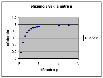
Finally, we can estimate the associated loss drop using the classic formula:
deltaP = K * ( gas density * intake velocity ^2 / 2)
We will develop a detailed illustration of the mining sector in the Applications section.
In order to obtain more information and/or request courtesy capacity plannings or case assessments, please send us an e-mail to answers@engineeringfundamentals.com cc.: balestie@umich.edu.
It is recommended to include a brief initial description of the case, ideally no more than one page, or project in progress / under study. The possibility of receiving and handling individual technical consultations has been foreseen but are limited as per availability. Alternatively make contact later on via sms/telephone +1 917 300 3024