INDUSTRIAL GAS FILTERS: FUNDAMENTALS
Broadly speaking, we can say that gas treatment, i.e., gas phase, can aim to achieve three objectives:
-
particulate removal, i.e. particle capture
-
removal of acidic constituents
-
removal of volatile organic material.
We have deemed it appropriate to restrict the scope of this booklet to technologies primarily aimed at achieving the first objective, i.e., particulate removal , and we can mention, without any order of preference:
-
cyclones
-
bag filters, also commonly referred to as fabric filters
-
venturi scrubbers
-
electrostatic precipitators
With varying degrees of efficiency, it is clear that any of the aforementioned alternatives contributes to the removal of, say, acidic constituents. However, the differences in efficiency, at least at the unit process level, recommend addressing the topic, specifically gas scrubbing, separately. Furthermore, we have chosen not to include volatile organic compound (VOC) removal technologies in our coverage of gas-phase filters.
Beyond individual characteristics, e.g., operating principle, construction materials, energy requirements, it is possible to compare or discuss the different alternatives of gas phase filters basically taking into account the characterization or distribution of particle diameters present in the flow to be treated .
Thus, if the industrial process involves particulates with diameters mostly greater than 10 µm, a cyclone separator stage will likely be specified. This framework may often be driven by an interest in material/product recovery , i.e., when the constituent has high value, e.g., silver. The capture efficiency of a given cyclone decreases as the particle diameter decreases, which may rule out this option in other contexts.
Both the competitive advantages and the contraindications of the different types of gas phase filters, i.e. cyclones, bag filters, venturi-type gas scrubbers, electrostatic precipitators, are reasonably well known today.
FUNDAMENTALS OF CYCLONE SEPARATOR DESIGN
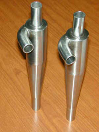
Cyclone separators, or cyclones, can be broadly classified into three types:
- Cyclones designed to handle large flows, where the priority is to limit pressure drop while processing large volumes of gas and
- Cyclones designed to achieve high or higher capture percentages or efficiency, commonly implemented as a multiplicity of small-diameter cyclones operating in parallel, called multicyclones
- conventional type cyclones
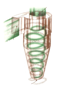
In general, cyclones are primarily used for removing particles with diameters around 10 µm. In many cases, they are used to reduce the load on subsequent filtration processes, e.g., bag filters.
In any case, and naturally taking into account the different energy requirements depending on the range of particle diameters to be captured, e.g. 2.5 µ, 10µ, 10+µ, cyclones are an extremely popular alternative , with no moving parts, very few maintenance requirements, low capital cost and interestingly dry collection.
Cyclone separators may not be recommended in applications involving material with adhesive or oily characteristics.
For construction/design purposes, a gas inlet velocity of 60 fps ( = 3600 fpm - 18.3 m/s ) can be taken, although naturally admission ranges can be considered, e.g., between 15 and 20 m/s.
Although there are important developments in the theory of cyclonic separation , mainly variants of Stokes' law, the use of a completely empirical formula has proven extremely convenient (and a reasonably good predictor in practice) :
efficiency = (d/dc)^2/ ( 1 + (d/dc)^2 )
being
d = particle diameter
dc = cutting diameter , defined as the diameter for which
50% of particles are captured
The introduction of the concept of cutting diameter , although perhaps a little artificial at first, nevertheless allows for excellent speculation of possible operating contexts, so we include a good working definition below:
dc = cutting diameter = ((9*Width*Viscosity/(2*3.1415*N*Vc*DensityP))^0.5/3.28)*10^6
being
Width = width of the intake window
Viscosity = viscosity of the gas
N = number of turns of the gas inside the cyclone, e.g. 5
Vc = entry/admission speed
DensityP = density of solid/particles
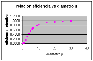
Once the cutting diameter has been determined , the expected capture or removal efficiency corresponding to each diameter can then be plotted, obtaining curves like the one illustrated below.
Finally, we can estimate the associated loss drop using the classic formula:
deltaP = K * ( gas density * intake velocity ^2 / 2)
We will develop a detailed illustration of the mining sector in the Applications section.
FUNDAMENTALS OF BAG FILTER DESIGN
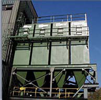
Gas phase filtration using bag filters is actually an adaptation of an intermittent or discrete process, i.e., filtration cycle sequences over a certain period of time, usually dictated by limits on the allowable pressure drop, and subsequent cleaning stages.
In order to achieve continuity of service, it has been decided to operate or design traditionally in one of two ways:
-
add additional capacity/compartment to that required in order to guarantee continuity while offline sections are being restored;
perform cleaning in extremely short intervals, e.g., between 0.03 and 0.1 seconds, increasing the frequency by alternating filtering and cleaning operations, e.g., according to a manometrically determined schedule.
The cleaning method employed somehow leads to the traditional classification of bag filters , namely:
-
mechanically cleaned bag filters (periodic shaking)
-
cleaning bag filters by reversing the air or gas flow
-
bag filters cleaned by short air pulses
While the classification may seem trivial, the particle collection mechanisms involved are fundamentally different . Whereas in mechanically cleaned bag filters and cycle reversal bag filters, filtration is achieved through the formation of a layer of the particulate material itself (the mesh or fabric is merely a substrate or support for the formation of this layer, or, if you will, a " pre-coat "), in short-pulse cleaned bag filter alternatives, the mesh or felt itself is responsible for the retention or capture of dust/particles.
In the case of mechanically cleaned bag filters, particulate removal is achieved through relatively vigorous shaking , which reduces the lifespan of the bags. In reverse-flow bag filters, the flow direction is cyclically reversed, resulting in a gentler operation. Short-pulse cleaning of bag filters is performed using abrupt bursts or shocks of air that impart a sinusoidal wave to the bag, not only causing particulate removal but also creating a new residual structure/layer.
In general, the operating speeds of pulse-cleaned filters are approximately twice those of periodic shake bag filters and reverse-cycle bag filters. While this naturally results in initial savings in terms of capital investment, the operating/energy costs associated with the compressed air (e.g., 0.03 to 0.1 seconds of air at 60 to 100 psig) required for cleaning can equal or exceed the cost of the main blower that drives or induces the gas phase to be filtered.
Both periodic shaking bag filters and reverse-cycle bag filters tend to primarily use filter fabrics or textiles/yarns , resulting in a clearly ordered texture. In the case of short-pulse cleaning bag filters, felts are usually employed ; that is, pressed fibrils forming a mat supported by an open backing fabric, generally creating more robust "sandwich" structures. This is another property that allows operation at the characteristically higher speed ranges of this type of filter. A wide variety of construction materials are available: polypropylene, polyester, polyamide, Ryton, Nomex, PTFE, Teflon, PET, and fiberglass.
As for the advantages of bag filter technology, it can be said that they constitute an alternative to gas phase filters with excellent capture/efficiency levels , are relatively insensitive to fluctuations in feed or load conditions, do not usually present corrosion problems (taking care to operate above the dew point), the operation is simple and high voltages are not required.
Bag filters may not be advisable in environments with extremely sticky (e.g., galvanizing plants), oily, or viscous particulate matter. In some cases, dust/particulate concentrations, e.g., close to 50 g/m³, can pose a risk of explosion or fire.
Although the sizing of bag filters is practically automated, for illustrative purposes it is possible to manually obtain an estimate of scale or order of magnitude.
In the case of a pulse bag filter, we can get an idea of the nominal speed V to be used using the following generic formula:
V = 2.878 * A * B * T^-0.2335 * L^-0.06021 * (0.7471+0.0853 Ln D)
being
A = a factor between 15 (tobacco, flour, grain, sawdust) and 6 (activated carbon, carbon black, detergents, powdered milk, soaps)
B = a factor associated with the service that must be fulfilled, e.g., conveying, venting, process, between 1 and 0.8
L = particulate load, eg 4 gr/cu.ft., (= 9153 mg/m3)
T = temperature, °F
D = average particle diameter, e.g. 7 µ
Typically the pressure drop ranges from 4 to 10 inches of water column , approximately between 4” and 8” for reverse cycle and between 3” and 6” for pulse cleaning bag filters.
VENTURI SCRUBBER FUNDAMENTALS
Venturi-type scrubbers allow for a high degree of particulate removal, even for smaller particle diameters, e.g., 2-3 µm, although with a consequent increase in energy requirements. For conceptual purposes, we can temporarily propose the following simplification to estimate the energy required for, say, 90% capture:
DeltaP (inches approx.) = 15” / diameter in µ
For example, retaining particles with a diameter of 0.5 µm would require approximately 30 inches. Obviously, in many cases, 90% removal is insufficient . To achieve 95% removal, operation should be around 60 inches.
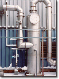
In venturi-type gas scrubbers, the gas stream containing the particles is accelerated toward a central section, with either a variable or fixed flow rate , at which point the gas comes into contact with the cleaning fluid (which is simultaneously absorbent in the case of gas scrubbing, although the contact time is too short to provide a truly effective scrubbing alternative). Upon contact, the scrubbing fluid is finely atomized into droplets, e.g., 80–100 µm, which trap the particulate matter with high efficiency. As these droplets decelerate, they coalesce, forming larger formations that can be directed to the capture zone, either a settling section or, typically, a cyclone separator.
The pressure drop across the venturi passage is a measure of the energy required to perform the cleaning or capture operation. The greater the pressure drop, the greater the capture efficiency, but also the higher the BHP required to operate the system.
To accommodate extremely variable gas flow rates, variable opening orifices or variable passages can be used, although in general the use of fixed opening units is preferred, that is, those associated with a primarily uniform flow rate.
Among the advantages of venturi-type scrubber towers we can mention the relative compactness of the equipment, the possibility of purifying gas flows of adhesive particles, the absence of secondary particle problems in handling, and relatively low cost.
Among the disadvantages of venturi-type scrubber towers are the transfer of a gas-phase problem to a liquid-phase problem, i.e., the need to deal with the scrubber tower effluent; increased instances of corrosion; relatively high maintenance costs; accumulation of solids; generation of steam plumes; opacity problems; and product recovery under wet conditions, i.e., whether or not acceptable to plant operators.
Due to the short contact time offered by venturi scrubber towers, their application is primarily for particulate removal. While scrubbing of acid gases is possible, the efficiencies are generally too low, so a counter-current scrubber tower is often installed downstream, thus solving the dual problem of high acid gas removal and low particulate removal. In a few cases, a tandem of venturi scrubber towers (two units in series) may be specified, likely with the aid of additional injection, such as steam.
The sizing of a venturi-type washing tower can be acceptably carried out by the following step-by-step procedure, developed by the joint effort of Yung, Calvert et al ., and ideally assisted by some type of spreadsheet:
-
Cunningham correction factor calculation
-
aerodynamic diameter calculation
-
calculation of idealized droplet diameter
-
calculation of inertial parameter Kpg
-
calculation of the Reynolds number
-
Calculation of the resistance coefficient Cd
-
calculation of parameter B
-
efficiency calculation = 1 – Pt
Being
Pt = 1/ e^(B*(4*Kpg+4.2-5.02*Kpg^0.5*(1+0.7/Kpg)* ArcTan((Kpg/0.7)^0.5))/(Kpg+0.7))
Repeated use of the above sequence for different particle diameters allows for the plotting of removal/efficiency curves, as shown below.
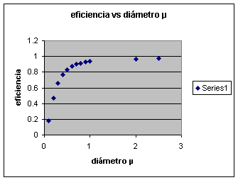
This model, called the infinite step model , has been shown to have a very good correlation with operating data of full-scale venturi-type washing units.
Fortunately, it is also possible to obtain a good approximation of the associated pressure drop . While we include several formulas below for estimating pressure drop, we will develop step-by-step illustrations for the case of an agricultural industry in the Applications section .
DeltaP = 8.24 * Vg^2 * L/G / 10^4 (SI)
DeltaP = 4.0 * Vg^2 * L/G / 10^5 (IP)
DeltaP = Vg^2 * RoL * QL / Qg
For the purpose of verifying the calculations, we can compare any result with a known baseline, e.g., the estimated energy required for, say, 90% capture, using the following simplification:
DeltaP (inches approx.) = 15” / diameter in µ
For example, retaining particles with a diameter of 0.5 µm would require approximately 30 inches of filter space. Obviously, in many cases, 90% removal is insufficient. To achieve 95% removal, the filter should operate at approximately 60 inches of filter space.
ELECTROSTATIC PRECIPITATOR DESIGN FUNDAMENTALS
The operating principle of so-called electrostatic precipitators , as particulate collectors, is relatively simple. It is basically a two-stage process :
-
to impart an electrostatic charge to the particles, with greater or lesser ease and
-
then collect them on plates of opposite polarity.
The charging stage is noticeably more agile, so the sizing of the electrostatic precipitator is largely determined by the second stage, i.e., collection on plates or panels of opposite polarity, which, through percussion mechanisms, achieve the detachment of the particulate matter.
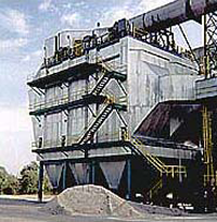
Among the operational problems that may arise, there may be one related to resistivity, a measure of the resistance of a particular object to exchange charge, that is, to accept or give up that charge.
In cases of high resistivity, we will encounter significant resistance to the transfer of electrical charge. Furthermore, the particulate matter adheres too strongly to the plates or panels, hindering the removal of the captured material.
In cases of low resistivity, the particulate matter readily acquires an electrostatic charge, but unfortunately, it also loses it just as easily, thus negating the capture mechanism. The particles then return to the fluid without being retained and continue on their path. This situation can be observed in the unburned carbon fractions of ash and carbon black.
There are at least two very traditional formulations for the sizing of electrostatic precipitators, namely:
1. Deutsch Anderson equation
efficiency = 1 - exp – (w*A/Q)
2. Modifications of the above, e.g., the Matts-Ohnfeldt equation
P = 1 – efficiency = exp – (w * A / Q)^k
Where w = migration/displacement speed, i.e. speed at which a particle, once loaded, migrates towards the collection plate.
Historically, the Deutsch Anderson equation has been very important, although it involves a number of significant omissions, namely:
-
It does not take into account the return of detachment to the gas phase
-
assumes that the size and speed are uniform for all particles
-
assumes that the gas phase distribution is uniform throughout the unit
-
It does not take into account particulate leakage.
Different manufacturers and specialists have proposed different types of corrections, for example, the use of effective precipitation rates based on historical data, or reducing the estimated efficiency by using, as Matts-Ohnfeldt does, a "de-rating" factor k in the original Deutsch Andersen formula , typically between 0.4 and 0.6
Historically very important definitions associated with an electrostatic precipitator configuration include, for example, the specific collecting area , defined as:
SCA = specific collector area = collector area / gas phase flow rate
e.g. m2 plate per m3/h gas phase
By using convenient multipliers, depending on the spacing between plates, the treatment time can be linked or derived in the dimensioning, a design criterion that somehow homogenizes the comparison between different units with "equal" SCA but different inter-plate spacings.
As with other gas-phase filtration processes, calculation models exist that allow for preliminary sizing estimates within +/- 20%. However, the formulas mentioned can be used to obtain guidelines or order-of-magnitude sizing estimates. Typically, the Matts-Ohnfeldt correction equation will result in more conservative designs than the Deutsch-Anderson equation, and is much more likely to reasonably predict the unit's actual performance.
As with the alternatives mentioned above, choosing the appropriate technology is a true specialty. This is especially important when technological or process changes occur within the plants or factories themselves. For example, there is a noticeable trend in pulp/kraft plants to operate with liquors with higher solids concentrations, e.g., increasing from 60 to 65% or even more. This leads to a greater propensity for the emission of submicron particles, which further complicates the design, application, and operation of electrostatic precipitators.
In any case, and for completeness, as with the other types of gas phase filters, we include numerical examples of electrostatic precipitator sizing in the Applications section.
In order to obtain more information and/or request courtesy capacity plannings or case assessments, please send us an e-mail to answers@engineeringfundamentals.com cc.: balestie@umich.edu.
It is recommended to include a brief initial description of the case, ideally no more than one page, or project in progress / under study. The possibility of receiving and handling individual technical consultations has been foreseen but are limited as per availability. Alternatively make contact later on via sms/telephone +1 917 300 3024